Description
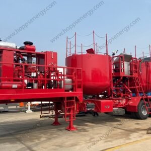
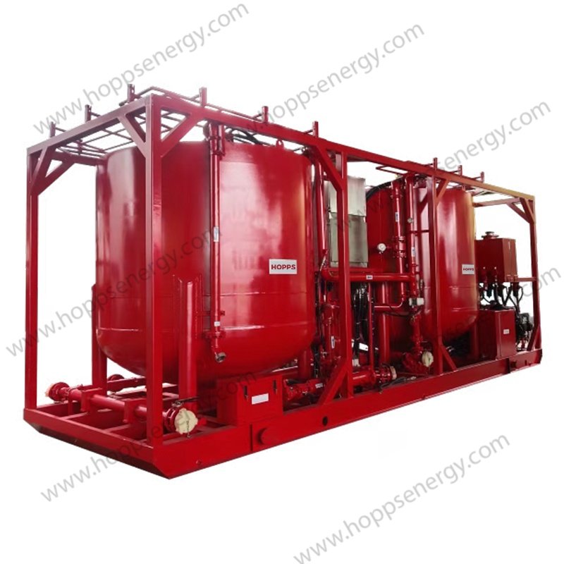
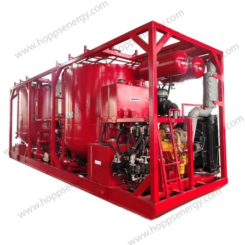
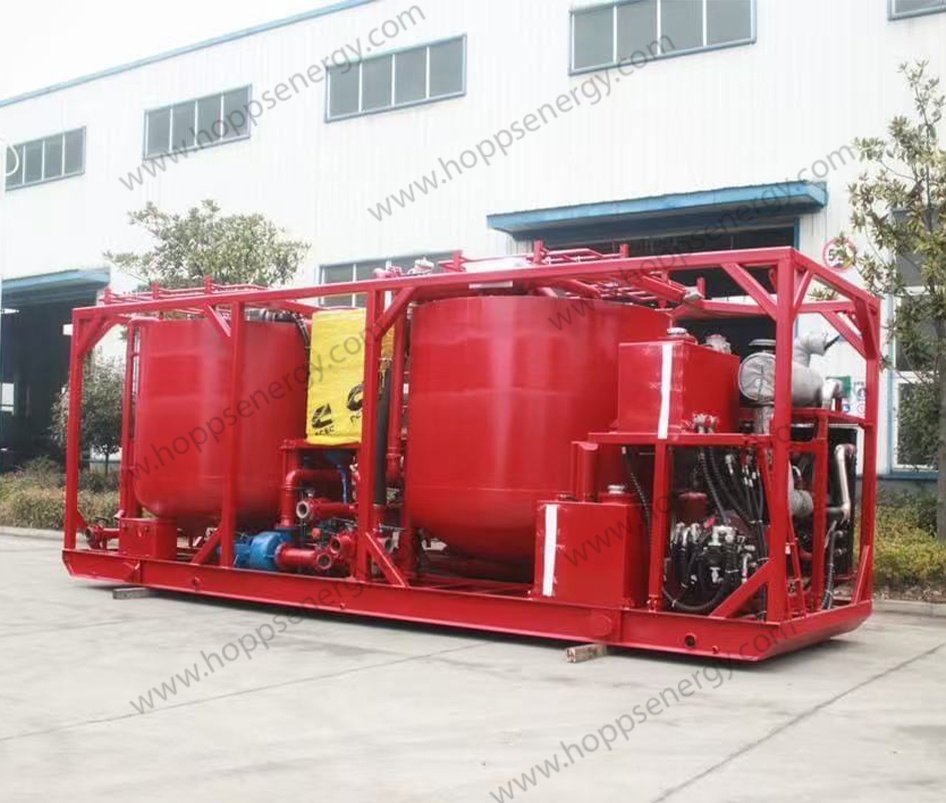
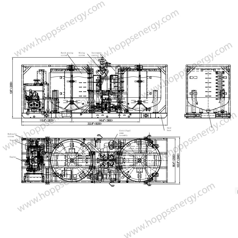
Cementing Batch mixer skid is mainly composed of integral skid frame, power system, batch mixing tank, manifold system, electrical system, centrifugal pump, hydraulic system, gas system, control system and so on.
Batch mixer skid is mainly used for batch mixing equipment for cementing operations in desert and land oil fields, and can prepare oilfield cementing slurry with high efficiency and high quality by mixing with agitator.
Continuous mixing: The mixing slurry can be pumped directly from the mixing tank through the transfer pump to the suction end of the large pump to complete the operation.
Batch mixing: The slurry continuously mixed from the mixing tank passes through two batches of mixing tanks successively to achieve batch mixing storage and continuous cementing operation.
Performance parameter
| Weight | 16000KG |
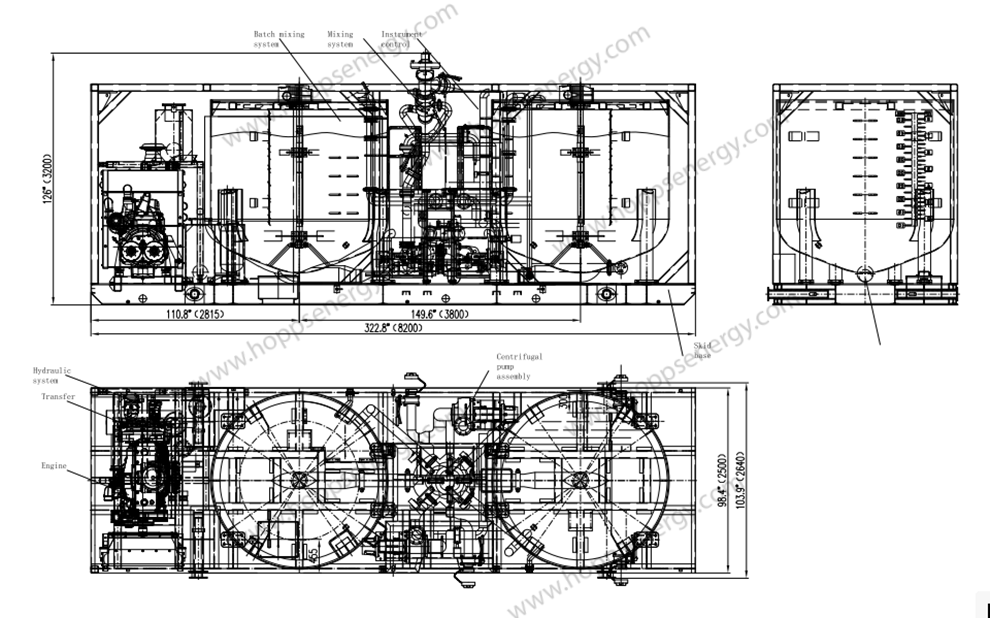
| Dimension | 322.8”X103.94”X126” |
| Maximum displacement | 3.2 m3/min |
| Density range | 1.0~2.3g/cm3 |
| Mixing capacity | 0.3~2.3 m3/min |
| Batch mixing tank volume | 2×8 m3(2X50bbl) |
| Operating temperature | -19ºC~45ºC |
Overall structure
| component | specifications | quantity |
| Integral Skid Frame | 1 | |
| Engine | QSM11-C360 | 1 |
| Transfer box | STIEBEL 4372 | 1 |
| Batch mixing tank | 8 m3(50 bbl) | 2 |
| Electrical system | 24 V | 1 |
| Centrifugal pump | 6×5×11 | 2 |
| Centrifugal pump | 4×3×13 | 1 |
| Hydraulic system | 1 | |
| Pneumatic system | 1 | |
| control system | 1 | |
| Manifold system | 1 | |
| Mixing system | 1 | |
| Stirring system | 3 | |
| Spreader | 1 |
Skid
The skid frame is an integral welded structure. The base uses I-steel as the main beam, and the stiffness of the skid seat should meet the use and lifting, and be easy to lift, without deformation due to use or lifting. Four lifting points (lifting lugs) are arranged on both sides of the skid seat, and the positioning of the lifting points (lifting lugs) is reasonable. The column is welded around the skid frame, and the frame space is formed.
The four corners of each skid seat are equipped with ISO international standard bottom corners for connecting with the lock tongue on the semi-trailer to install and fix the batch-mix skid on the semi-trailer. The skid base oil tray has an inclined Angle to facilitate centralized oil collection. A plurality of ball valves with residual liquid discharge (set at the lowest value, water or other liquids can be automatically discharged when placed horizontally).
Engine
| Model | QSM11-C360 |
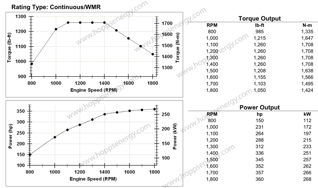
| Power | 268 kW(360 hp/1800rpm) |
| Max. torque | 1708 Nm(1,400 rpm) |
| Start mode | Electric motor start |
| Cooling method | Fan Radiator Cooling |
| Throttle Control | Electric |
| Flameout method | Electric |
| Exhaust | Silencer (with rain cap) |
|
Other configurations |
24 V DC power supply generator, thermostat, air filter, air filter rain cap, etc. Weather shield, turbocharger(thermal-protective coating), silencer(thermal-protective coating), exhaust pipe(thermal-protective coating) |
Transfer Case
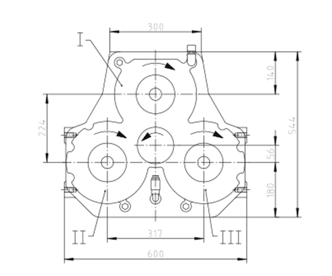
| Model | STIEBEL 4372 |
| Max. Input Power | 400 kW |
| Max. input speed | 3500rpm |
| Max. power per output port | 210KW |
| Max. output torque per output port | 1000 Nm |
| Quantity of output ports | 3 |
| Quantity of input ports | 1 |
Electrical system
The power supply of the electronic control system is provided by the battery and the generator of the engine, providing power for instruments, engine start, stop, lighting, etc. The lighting device is easy to operate at night and observe and measure the liquid level inside the tank.
Mixing system and manifold system
The jet type high-energy mixer is a circulating mud mixer with extremely high mixing capacity. There is one jet water inlet, two circulating cement slurry inlets, one dry cement inlet, and one mud discharge outlet.
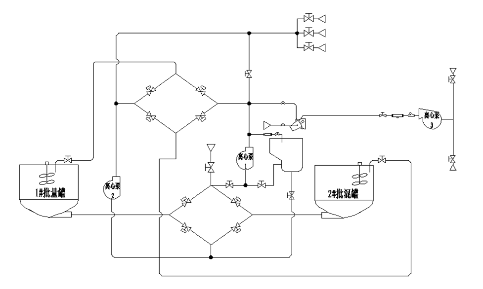
During operation, clean water is sprayed into the high-energy mixer through the clean water manifold, and the high-speed flowing jet causes negative pressure to be generated in the high-energy mixer; The dry ash is controlled by the upper ash manifold through a butterfly valve. After being mixed once in the high-energy mixer, the dry ash and water enter the mixing tank through a diffusion tank. The stirred mud is mixed twice and multiple times through a circulating centrifugal pump. The mud continuously mixed from the mixing tank passes through two batches of mixing tanks to achieve batch mixing and storage. The mixed mud is injected into the three cylinder plunger pump by the circulating pump.
During operation, clean water is sprayed into the high-energy mixer through the clean water manifold, and the high-speed flowing jet causes negative pressure to be generated in the high-energy mixer; The dry ash is controlled by the upper ash manifold through a butterfly valve. After being mixed once in the high-energy mixer, the dry ash and water enter the mixing tank through a diffusion tank. The stirred mud is mixed twice and multiple times through a circulating centrifugal pump. The mud continuously mixed from the mixing tank passes through two batches of mixing tanks to achieve batch mixing and storage. The mixed mud is injected into the three cylinder plunger pump by the circulating pump.
The suction port of the clean water centrifugal pump is a 4 “Fig206 union port, which can suck fluid from external water sources and pump it into a high-energy mixer to provide the required high-pressure clean water for the mixing process.
The circulating centrifugal pump sucks in mud from the bottom of the batch mixing tank, and most of the mud is pumped to the high-energy mixer for secondary or multiple cycles.
The switching valve between the two circulation pumps can be opened or closed to achieve mutual replacement of the two circulation pumps under specific conditions.
All butterfly valves in key parts of the manifold adopt pneumatic switches, and the actuators are concentrated on the operating platform for easy operation; The flowchart is located below the butterfly valve actuator for easy observation and has corresponding numbers.
The lower ash butterfly valve is manually controlled, and the upper ash port adopts a 4 “FIG206 female union.
Batch Mixing Tank
Effective volume of batch mixing tank:2×8m³(2 x 50bbl)
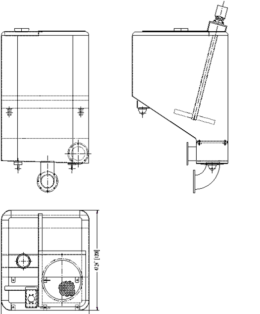
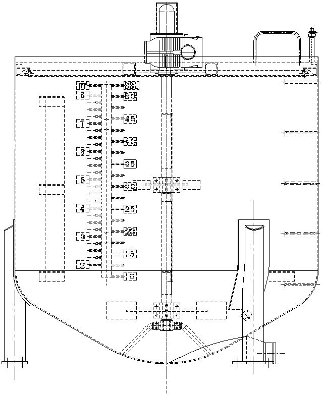
Each batch of mixing tanks is equipped with one high-power mixer, which adopts a double-layer blade structure and has excellent mixing effect, which can prevent the settlement and agglomeration of cement slurry. The tank is equipped with a liquid level gauge, measured in barrels (BBL) and cubic meters (m³) Is the scale
Lubricating system
The centrifugal pump packing lubrication adopts an air top oil lubrication system, and the centrifugal pump packing provides continuous cooling lubricating oil. Main components: lubricating oil tank, pressure reducing valve, switch, needle valve, one-way valve, ball valve, and pipeline.
Hydraulic system
The engine drives 4 sets of hydraulic pump systems through the transfer box, and the hydraulic pump drives the hydraulic motor, forming 3 independent open hydraulic systems to drive 3 centrifugal pumps, 1 independent open system to drive 2 mixers, and 1 independent open system to control the ash and water inlet valves of the high-energy mixer.
The mixing motor of the batch mixing tank drives the mixer through a reducer.
The hydraulic system is equipped with a hydraulic oil radiator to control the hydraulic oil within the optimal operating temperature range.
Hydraulic pumps, hydraulic motors, remote control valves, and other hydraulic components are all selected from well-known domestic and foreign brands, with safe and reliable quality and performance.
Pneumatic system
The air circuit system mainly consists of an air compressor, gas storage cylinders, filtration and pressure reducing valves, pneumatic butterfly valve actuators, and pipelines. The air source is provided by the engine driven air compressor, which mainly controls the opening and closing of the butterfly valve.
Control System
The power supply of the electronic control system is provided by the battery and the generator of the engine, providing power for instruments, engine start, stop, lighting, etc. The lighting device is easy to operate at night and observe and measure the liquid level inside the tank.
All hydraulic and pneumatic control units, engine control devices, and butterfly valve pneumatic switches are centralized on the instrument console and its surroundings, making operation convenient. The operation console is made of stainless steel plate, which is beautiful and reliable.