Description
Overall Structure and Technical Specifications
Product Introduction
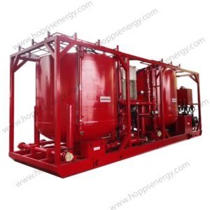
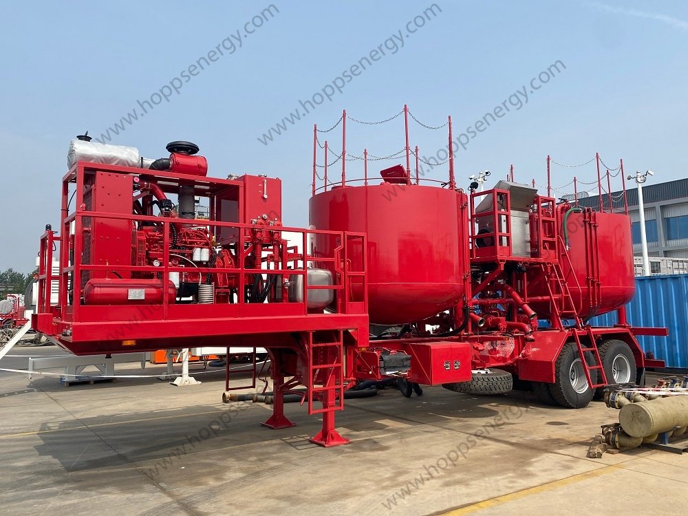
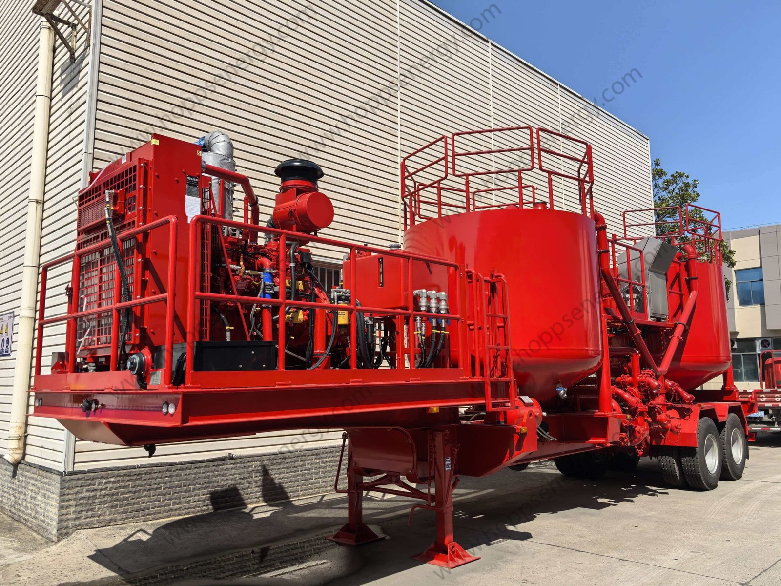
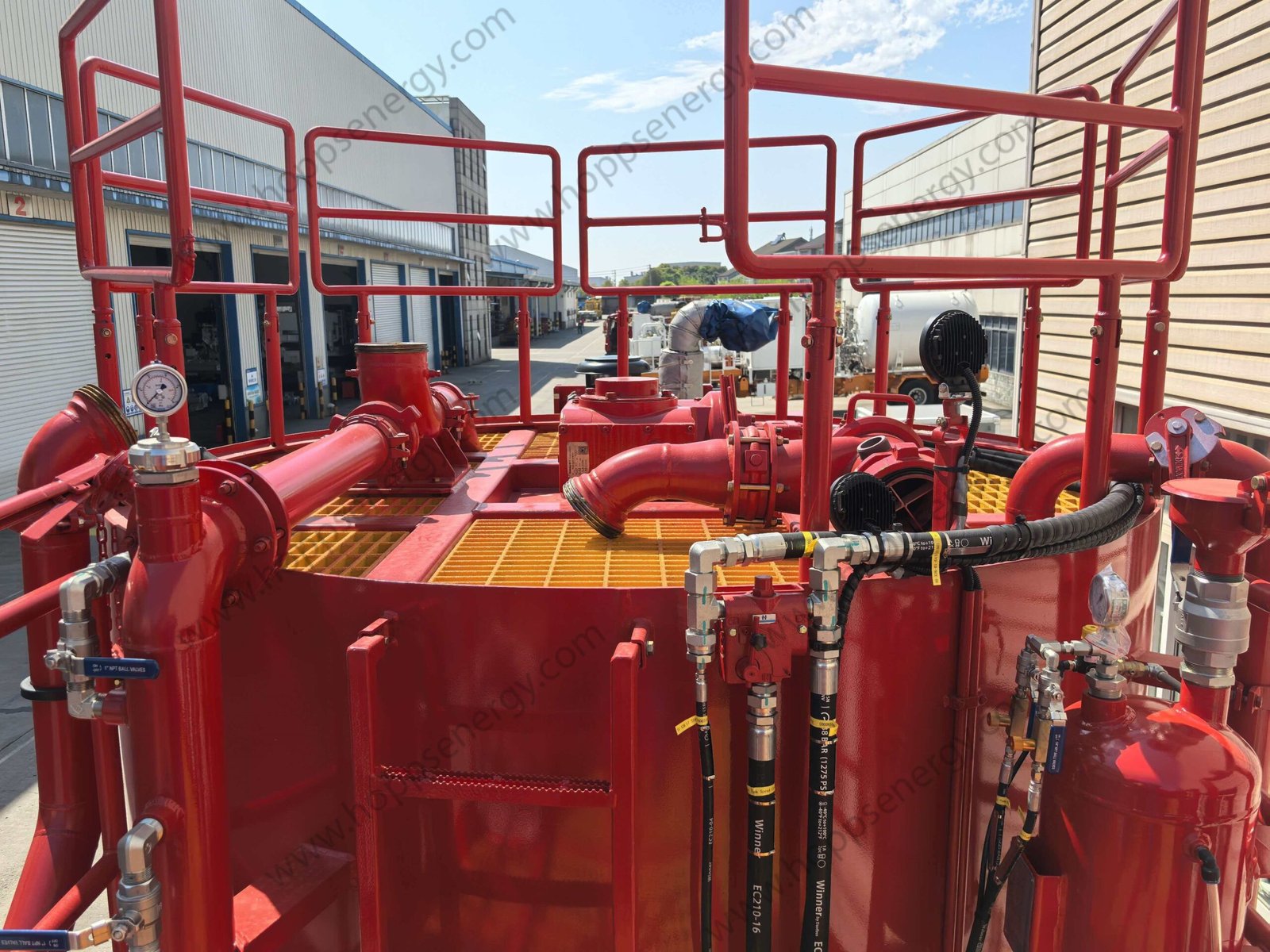
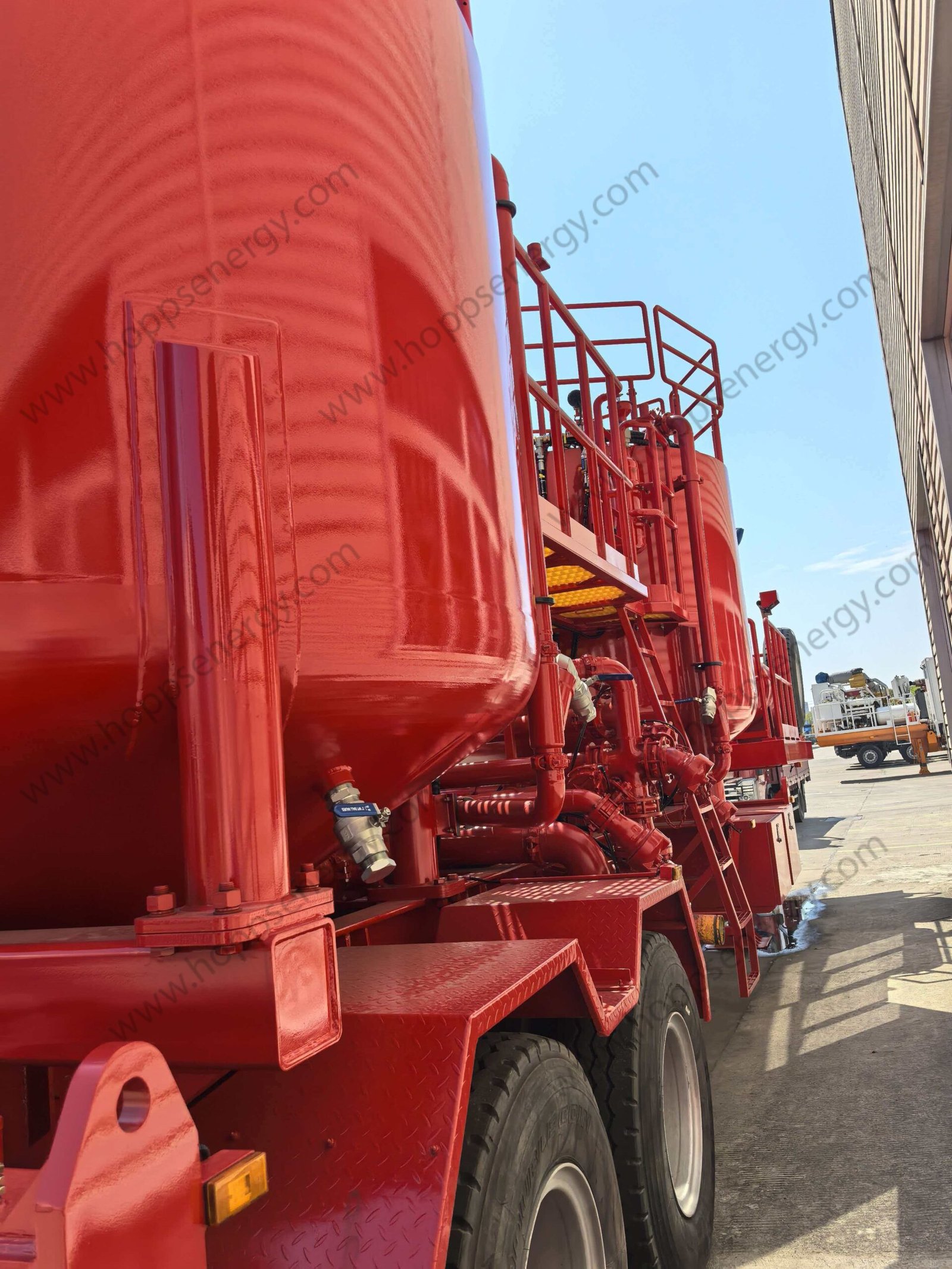
Batch mixing trailer is mainly composed of trailer chassis, power system, 2x60BBL batch mixing tank, auto mixing system, piping system, closed hydraulic system, pneumatic system, lubrication system, electrical system and so on.
The device is powered by a Cummins QSM11-C360 diesel engine, which drives the hydraulic system through a STIEBEL 4373 transfer case, and then provides power to three centrifugal pumps and a mixing motor.
The equipment’s operating process is as follows: High-pressure clean water from the water supply pump (4X3) enters the high-energy mixer to form a jet stream, creating a certain negative pressure that draws in dry ash. The dry ash is then thoroughly wetted and mixed in the high-energy mixer before entering the slurry tank. The initially mixed slurry is then returned to the mixer by the circulation pump (6X5) for secondary and multiple cycles until the set slurry density is reached.
The mixed slurry is then pumped to the batch mixing tank by a transfer pump (the second 6X5 centrifugal pump). The batch mixing tank is equipped with an agitator to prevent slurry separation and sedimentation. For special formula slurries, additives can be manually added through the funnel at the top of the batch mixing tank and mixed by the circulation pump.
Once the slurry in one tank is mixed, it is pumped to the plunger pump of the cementing pump truck (skid) by the injection pump, while the mixing of the second batch of slurry begins in the other batch mixing tank, enabling continuous operation.
This equipment can meet several operating conditions:
Continuous mixing: The mixed cement slurry can be directly pumped from the mixing tank to the suction end of the main pump via the transfer pump to complete the operation.
Batch mixing: The slurry from the mixing tank passes through two batch mixing tanks in sequence, enabling batch mixing, storage, and continuous cementing operations.
Mixing of special slurries: For special formula slurries (such as high-density slurries), the conventionally mixed slurry can be used as the base fluid, and weighting agents can be manually added through the funnel at the top of the batch mixing tank and mixed by the circulation pump within the batch mixing tank.
Performance Parameters and Overall Structure
| Weight | 23000KG |
| Dimension(ft) (L*W*H) | 11500*2500*4200 |
| Engine Power | 405HP/2000 RPM |
| Continuous Mixing Capacity | 0.3~2.3 m3/min |
| Density Range | 1.0~2.3g/cm3 |
| Continuous Mixing Density Accuracy | +/-0.02 g/cm³ |
| Batch Mixing Tank Volume | 2x60BBL (2×9.5 m3) |
| Mixing Tank Volume | 8BBL (1.3 m3) |
| Operating temperature | -20ºC~55ºC |
| Component | Specifications | Quantity |
| Trailer chassis | 1 | |
| Engine | QSM11-C360 | 1 |
| Transfer box | STIEBEL 4373 | 1 |
| Batch mixing tank | 60BBL (9.5 m3) | 2 |
| Auto Mixing System | Control Panel+OpenHCC+High-energy Mixer+Mixing Tank+Densimeter | 1 |
| Hydraulic System | Closed Hydraulic System | 1 |
| Pneumatic system | 1 | |
| Lubrication System | 1 | |
| Electrical system | 24 V | 1 |
| Centrifugal pump | 6×5×11 | 2 |
| Centrifugal pump | 4×3×13 | 1 |
| Manifold system | 1 |
Trailer Chassis
The semi-trailer is a specially designed chassis vehicle adapted for oilfield operations with a load capacity of 30 tons. It is equipped with service brakes, parking brakes, and emergency brakes, and utilizes a 4S/2M type A air tank BS anti-lock braking system. Tires: 385/65R22.5-20PR (8 tires), 1 spare tire; Air tanks: 2 x 50L tanks.
| No. | Name | Parameters |
| 1 | Axle | 2 axles |
| 2 | Traction Pin | 2” (50#) |
| 3 | Operating Weight | 30,000 kg |
| 4 | Tires | 385/65R22.5-20PR |
| 5 | Frame Outriggers | 28tons |
| 6 | Wheelbase | 1,400 mm |
Engine
| Model | QSM11-C360 |
| Power | 268 Kw |
| Max. torque | 1,708 N·m |
| Start mode | Electric |
| Cooling method | Fan Radiator |
| Throttle control | Electric |
| Flameout method | Electric |
| Exhaust | Muffler (with Rain-proof Cover) |
| Other configurations | 24 V DC Generator, Thermostat, Air Filter, Rain-proof Cover of the Air Filter, Weather Shield, Turbocharger (Thermal-Protective Coating), Silencer (Thermal-Protective Coating), Exhaust Pipe (Thermal-Protective Coating) |
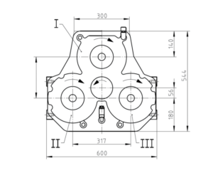
Transfer Case
| Model | STIEBEL 4373 |
| Max. Input Power | 400 kW |
| Max. input speed | 3500rpm |
| Max. power per output port | 210KW |
| Max. output torque per output port | 800 Nm |
| Quantity of output ports | 3 |
| Quantity of input ports | 1 |
Batch Mixing Tank
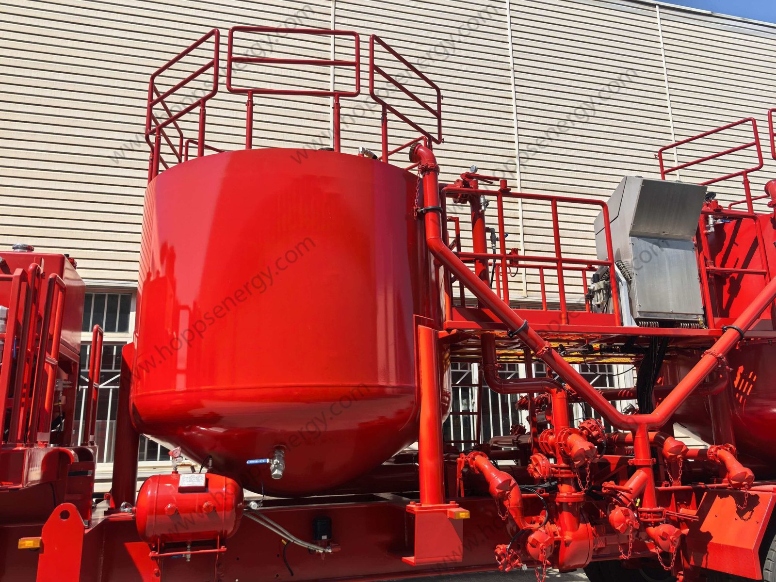
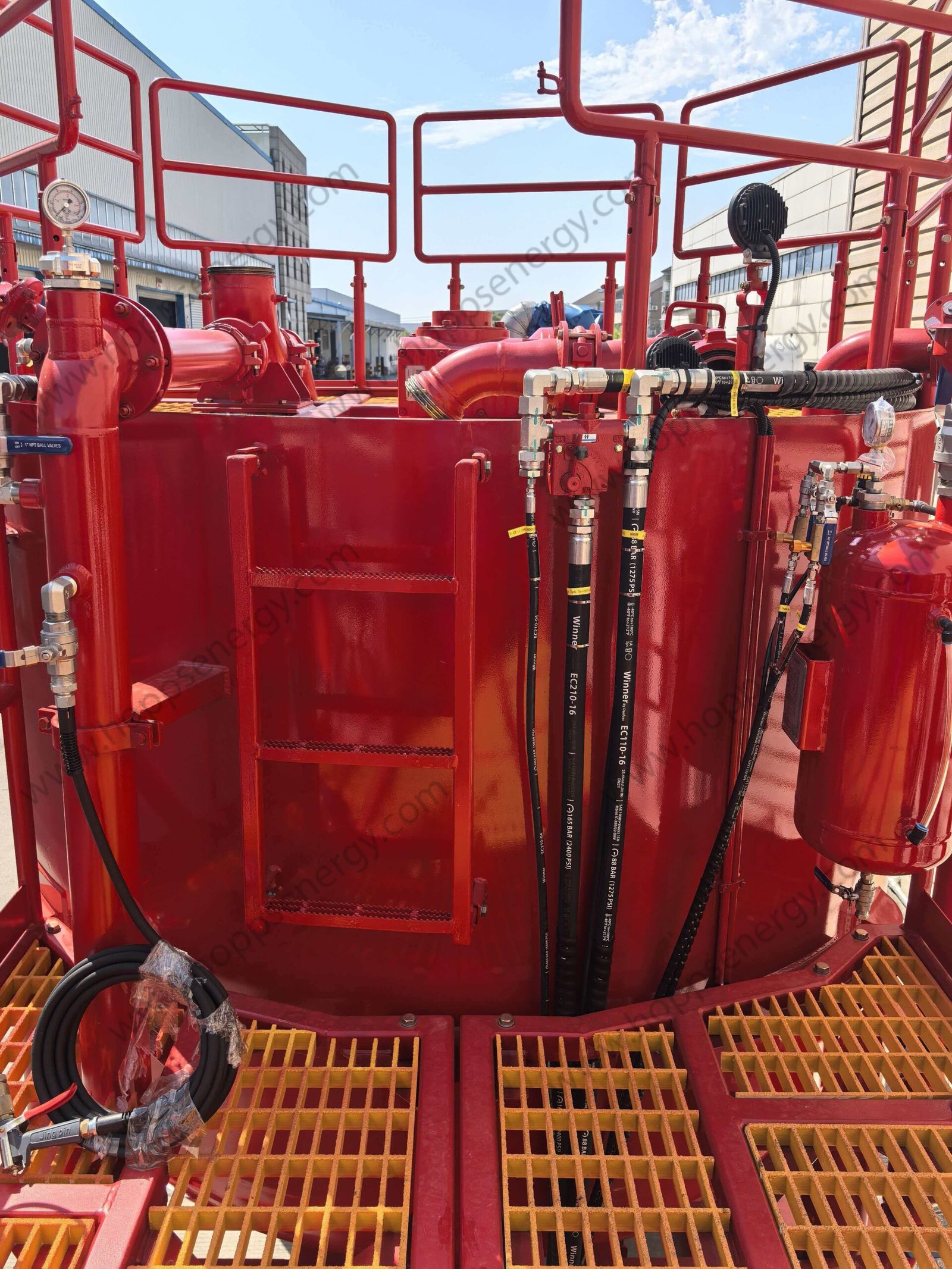
The two 60 BBL (9.5 cubic meter) batch mixing tanks have a circular open top and a conical bottom, which prevents dead zones in circulation and flow, ensuring no residual mud after operation. Each tank is equipped with a mixer, with a rotation speed set at approximately 75 RPM. The double-layer mixing design prevents cement slurry settling and clumping, resulting in a more uniform mixture. The top of the tank has a loading hopper to accommodate the addition of bagged dry cement and/or special mud additives. The tank also features a liquid level indicator and a light on top for nighttime operation. The batch mixing tanks are made of 8mm thick 16Mn steel.
External cleaning: A flushing hose and spray gun are connected to the clean water pipeline to clean the outer surface using a jet of water.
Internal cleaning: High-pressure clean water is introduced into the hollow shaft of the batch mixing tank agitator through a rotating sealing joint. As the agitator rotates, the water jet automatically cleans the inner surface of the tank.
Auto Mixing System
The auto mixing system mainly consists of operation control panel, control system (OpenHCC), high-energy mixer, mixing tank (8 BBL), density meter, powder discharge valve, diffusion tank, clean water centrifugal pump, circulation centrifugal pump, transfer centrifugal pump, stirrer, and slurry manifold.
The high energy required for mixing is supplied by a clean water centrifugal pump and a circulating centrifugal pump. Dry powder from the powder hopper (powder truck) is pneumatically conveyed into the powder discharge valve, and the powder discharge rate can be adjusted manually or via a computer-controlled proportional powder discharge valve. The high-speed water jet from the high-energy mixer not only creates negative pressure to draw in the dry powder but also ensures maximum wetting of the dry powder. The circulating centrifugal pump facilitates secondary or multiple circulation of the cement slurry between the mixing tank and the injector. The diffusion tank is used to remove gases from the initial slurry and to remove dust from the mixing tank. The hydraulically driven mixing blades in the mixing tank effectively increase the mixing energy and prevent slurry sedimentation. The mixed slurry is then pumped to the batch mixing tank by a transfer pump. After initial mixing in the mixing tank and buffering and stirring in the batch mixing tank, the cement slurry becomes very uniform, ensuring high-quality mixing.
Dry cement is fed into a high-energy mixer via a cement hopper, with the cement flow controlled by an eccentric discharge valve. Clean water is pumped into the mixer by a jet pump, and the water volume is controlled by a water valve and measured by a flow meter. The mixer’s core is controlled by a PLC microprocessor from AB (or Siemens). This microprocessor quickly responds to the measured clean water flow and slurry density, compares it to the set slurry density, and calculates and adjusts the position of the eccentric discharge valve to control the cement flow. Simultaneously, the system’s unique “feedforward predictive control” program quickly responds to density changes and automatically adjusts the density to within the set range before any significant density errors occur. During operation, this program can sense three possible changes: changes in discharge rate; changes in the set density; and changes in cement flow rate caused by irregularities and/or reductions in dry cement transport.
In simulation mode, the computer can provide system self-testing to verify the working status of all manifolds, cables, flow meters, hydraulic systems, feedback systems, and the microprocessor itself. This system can also be used to train operators in manual and automatic density control.
Operation Control Panel
The operating platform offers a wide field of view, allowing operators to monitor the entire equipment during operation. The control cabinet is made of stainless steel, and the control panel is equipped with various valves and instruments for controlling the entire equipment, including: engine instruments (speed, water temperature, oil pressure), engine start/stop and throttle control, hydraulic gauge, computer operating screen, centrifugal pump control valve assembly, mixing motor control valve, pneumatic butterfly valve control valve, workbench lighting, and air horn.
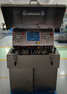
The system utilizes the advanced OpenHCC automatic mixing control system to monitor and control the entire equipment, including controlling the engine’s start/stop and speed, controlling the position of components such as the water valve and ash discharge valve, collecting sensor data such as flow rate, liquid level, pressure, valve position, and density, and calculating construction process data based on the collected sensor data.
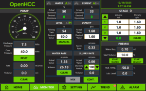
The engine control function mainly includes starting (electric start), stopping, speed control, and emergency systems for the engine on the test bench. The control panel is equipped with Murphy gauges to display parameters such as engine oil pressure, coolant temperature, load rate, speed, and fuel consumption rate.
The fresh water valve control function mainly controls the opening of the fresh water valve. There are three control modes for the fresh water valve: automatic, manual, and hydraulic. In automatic mode, the controller collects signals such as fresh water flow rate, fresh water valve position, density, and displacement, and automatically calculates the fresh water valve position based on the set density to meet the fresh water flow rate requirements for the set mud density. In manual mode, the opening of the fresh water valve is controlled via a manual lever on the control panel. In hydraulic mode, the opening of the fresh water valve is controlled via a hydraulic handle.
The dry powder discharge valve control function mainly controls the opening of the dry powder discharge valve. There are three control modes for the dry powder discharge valve: automatic, manual, and hydraulic. In automatic mode, the controller collects signals such as fresh water flow rate, dry powder discharge valve position, density, and displacement, and automatically calculates the dry powder discharge valve position based on the set density to meet the dry powder flow rate requirements for the set mud density. In manual mode, the opening of the dry powder discharge valve is controlled via a manual lever on the control panel. In hydraulic mode, the opening of the dry powder discharge valve is controlled via a hydraulic handle.
The premixing function is a key link in the batch mixing equipment control system, mainly used to initially mix cement, water, and additives in the mixing tank to ensure the uniformity and stability of the cement slurry. Its core functions include:
Uniform mixing: Premixing ensures that all components of the cement slurry are fully mixed, avoiding clumping or unevenness, and improving the quality of the cement slurry.
Optimized performance: The premixing stage allows for adjustment of parameters such as density and viscosity of the cement slurry to meet the requirements of downhole operations.
Improved efficiency: The premixing stage reduces on-site mixing time and improves the overall efficiency of the operation.
The liquid level control function mainly controls the liquid level in the mixing tank. According to user settings, the PLC controller collects sensor data such as mixing tank liquid level and flow rate, and then calculates the required valve openings for the clean water valve and the ash discharge valve using a PID algorithm, thereby ensuring a constant liquid level in the homogenization tank.
The density control function primarily focuses on real-time and precise control of the cement slurry density. Even when the flow rate changes, the system can respond quickly to ensure the stability of the slurry density. It can also quickly react and adjust when the density of the initial and final slurry changes.
Piping System
The process manifold system is designed for extremely flexible and convenient operation. By switching the valves on the manifold, it is possible to circulate and transfer liquids, allowing two centrifugal pumps to draw liquid from any of the batch mixing tank, the mixing tank, and an external water source, and then pump the liquid to any of the batch mixing tank, the recirculation mixer, and an external pump truck. The external water supply line uses a 4″ pipe, with a 4″ standard English union connection and a threaded union connector.
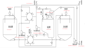
Hydraulic System

To ensure the independence and integrity of the equipment, the device is also equipped with pneumatic, lubrication, and electrical systems.
The pneumatic system’s air source is provided by an engine-driven air compressor and mainly consists of an air tank, safety valve, oil-water separator, piping, and other accessories. It primarily supplies air to the butterfly valve operation and lubrication system.
The centrifugal pump packing lubrication system is a gas-pressurized oil type, mainly composed of an oil tank, separation switch, distribution system, and piping.
The electrical system power is supplied by the engine generator and is used for engine instrumentation, the computer system, and the equipment lighting system.